Aidan Williamson Log 2013

Old Logs:
Links:
December 2013
12/20
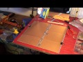
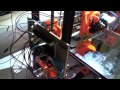
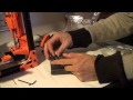
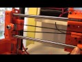
Day 2 of Water_Wheel_Transplanter build. The frame is coming together. The vertical tank supports, trailer hitch arm, and wheel mount arms have been attached to a 48" crossbar. It took a long time to prepare for welding. We ended up making a mistake with the second wheel mount arm. It was misaligned after three passes of welding. I had to cut it off, grind it all down, and reattach it. I ended up propping it on the ground with a lever as I tacked it in the right position. We prematurely tried a destructive test of the trailer hitch arm weld and saw that the material we are using bends a bit too easily for comfort. I attached gussets to that joint after I saw the bending and plan to add supports all over for strengthening the material. I worked until 9:30 and had some dinner then fell right asleep so I'm writing this the morning after.
12/19
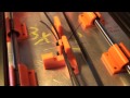
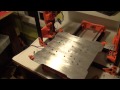
Day 1 of Water_Wheel_Transplanter build. 5 Shelf frames were made: One 62"x21" , two 41"x21", and two 20"x10x from 1.5"x2" and 1"x1" angle stock recovered from fencing, 1/8". Rust had to be cleared off and it was not a pleasant experience having to wear a mask while grinding with a wire brush. Gabi and I worked next to each other between a two tables where the 10' lengths were suspended. 45 Degree angles were cut on an abrasive saw very easily. I cut with the abrasive saw while Gabi cleaned the cuts and the area around them for welding with a hand grinder. This process took about an hour. Then Gabi went to get a tongue hitch from the woods while I welded the shelves together with a 120V MIG welder and a square rule. This took about an hour and a half as I did it slowly so that I could get the feel for the welder here. I'm using .023 wire and about 18cfh of argon and getting good penetration.
I also looked at the stock we will be using for the frame. It seems to be 3"x1" tube which was cut along the 1" face and bent outwards. I think it will be strong enough but the shape is difficult to work with. I will just have to cut irregular angles with the saw I guess. Perhaps no problem at all.
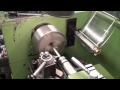
For the wheels I will use this spindle welded to the frame in two places for this idler hub. The wheels will be sourced from craigslist most likely.
12/11
Boom Doneski

12/10
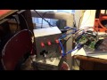
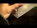
Been sick, not working on much. Finals week is here as well. I tested the hot end thermistor and resistor. The thermistor performed well but the modified resistor desoldered and opened. I ordered the proper part from DigiKey. I also ordered my plastic. I hope the quality is inversely proportional to it's low price...
Video of thermistor installation, first heating, and of the heated bed warming up to 60 degrees.
12/1
Ugh, December and I haven't finished...
It was silly of me to suggest to use an electromechanical relay for the heated bed switching since it would be noisy and wear out. Here is an open source solid state relay which could work instead of mouser part number 653-G3E-220T-US12.
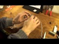
Upper plate and lower plate for the Budaschnozzle 2.0 have been finished. I made them by hand.
November 2013
11/29
Heated bed finishing touches applied. It is now mounted on the TAZ. I raised the temperature to a maximum of 108 degrees Celcius. Another option is to use a step down transformer and a relay (perhaps Mouser part number 769-HL1-HP-DC12V-F) to use more power. This configuration can print PLA and I have yet to determine if it will print ABS.
I made a nozzle at school but I need to make another one because I drilled the hole 3x too wide. First Print ETA 1.5 weeks.
11/21

PTFE feed tube has been made. I may need to redo it due to an oversized inner diameter. I will have to test it first.
11/19
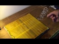
Here are the scanned calculations I mentioned in the Ghetto HBP video.

11/18
Heated bed finished!! I got to post my first thingiverse entry!
The mount plate for the buda just needs to be tapped in three holes and then it will be done. Here is how it was done:
The part was programmed and partially milled from 3/4" stock on a desktop cnc mill
The four holes were center drilled on the cnc mill
The part was squared on a bridgeport
The part was holes were drilled while allowing the part to float on parallels
Most of the excess material was removed on a vertical bandsaw (copper clamp used as heatsink)
The part was milled down to 3/8"
The center hole was drilled and countersunk
Burrs were removed
Holes will be tapped
Sorry I didn't get any video of it...
11/13
I used a dividing head on a vertical mill to turn some 6061 round bar into 1/2" hex stock. I got some footage but i won't post it until I finish the nozzle.
Working on the heated bed. I hope to have that finished by next weekend because i'll be backpacking the next 4 days.
11/12
Decided to make the Buda Nozzle out of some hex stock instead of using a cap nut. Apparently cap nuts are made from two pieces of metal joined together (the nut part and the cap part) and have a tendency to come apart. Also, I can make the nozzle out of aluminum this way.
I have also been reading about pcb milling on a 3d printer. The RepRap wiki has some information about it - mostly what software to use - and gives some links to some external sites. Bernhard Kubicek says on his site that he doesn't believe in PCB Milling on a belt-driven machine. This is because they allow "high frequency xy oscillations" which can lead to copper chips being left in the traces. Be sure to check out his site if you are interested in the HydraFabber design.
11/10
I removed most of the embedded youtube videos and replaced them with clickable links using the code found in Wiki Instructions
11/7
I need to take good data on the sound and power produced/consumed by my printer. I'll have a procedure for those experiments coming soon...
11/6
Threaded extension made. Also, my professor showed up with a fat chunk of teflon for the PTFE tube and heatsink washer spacers.
I need to start working on the heated bed. I have Gabi working on a 12x12 square of wool (ignition temperature 600 degrees Celsius) for an insulator between the glass and the ghetto hbp.
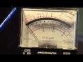
I modded an atx psu for use with the motors. I need to do another one. I also need to be careful and take some data on the voltages coming out of these power supplies. Some panel voltmeters would be useful...
11/5
Not much work has been done on the Taz in the past week. I finished the heater block for the Budaschnozzle and found out that my professor has some machinable teflon for the feed tube. I am currently gathering information for atx power supply usage. I need to decide whether to use two ~200w supplies or one 460w supply for my build. The 460w supply belongs to a friend so I would have to use a breakout board to harness its power. This would have to be made by me since there are no high current breakout boards available. The hard part is connecting 24pin molex power connectors to protoboards since the pin spacing is 4.2mm instead of the standard 2.54mm (1/10"). If I were to use two power supplies then I would have different voltages coming out of each one and I don't know how that would affect the RAMBO board. I think that the motors/logic and heated bed systems are separate since they require separate power in connections. I could use one supply for Mosfets and Motors & Logic and I could use the other supply for the heated bed. I could be fun to toy around with those old supplies and customize them with analog voltmeters or something...
October 2013
10/29
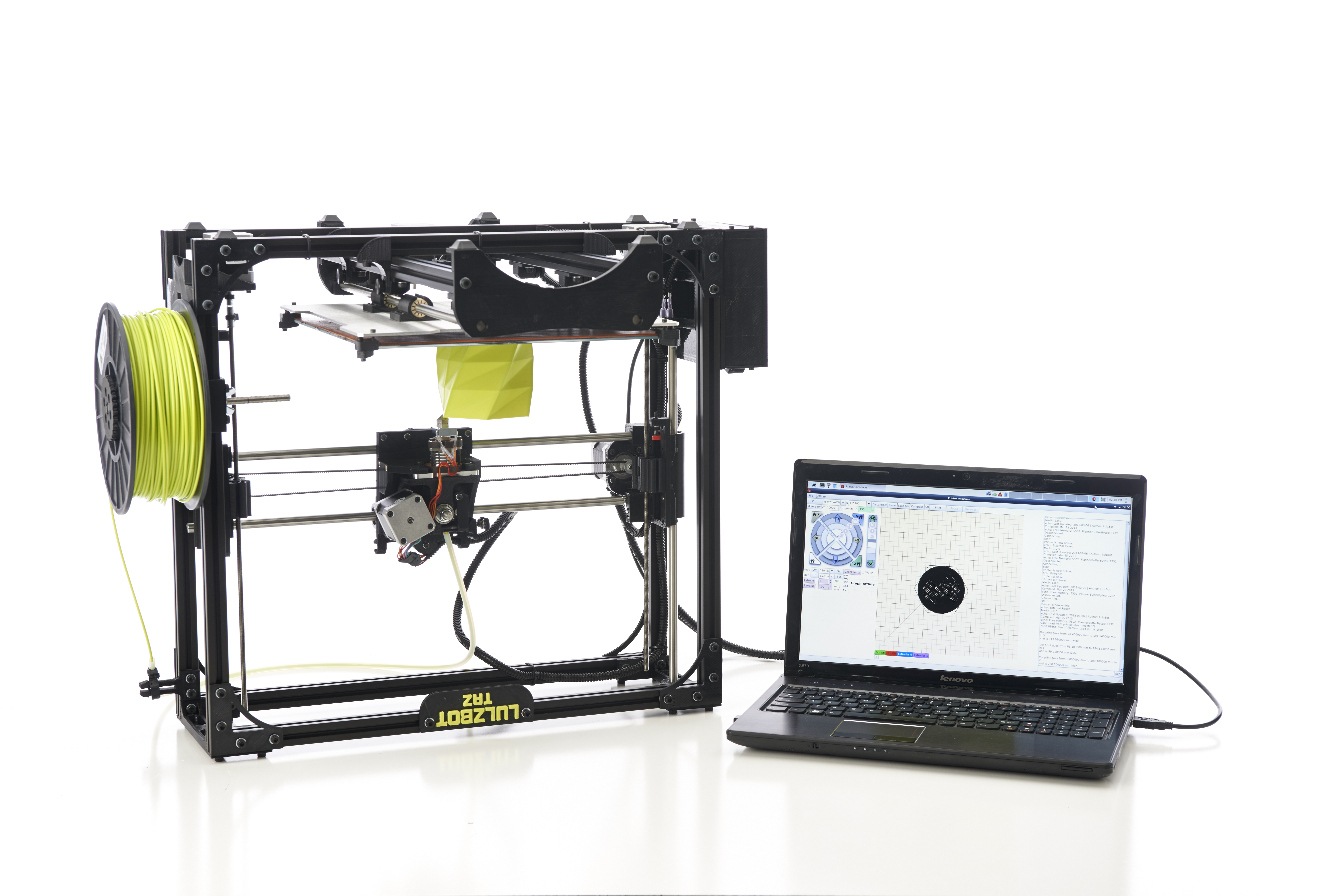
My TAZ costs HALF the cost of a MendelMax 2.0 kit, but will have up to 1.57 times the build volume. Not to mention it will have milling and laser cutting abilities...
The heater block is underway at school.

10/24
I followed the guide embedded in the 10/20 post to assemble this.

And here's a quick update on the buda.
10/23
Y- Bed is almost done! Just need to mount the pulley and get the motor pins wired. The template I uploaded on 10/20 is not accurate; I need to redo it.
I will NEVER use a jigsaw to cut aluminum again! It took a least 2 hours and I still have a headache a day later...
10/20
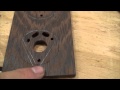
Use this as a template for making the wooden upper and lower plates on the budaschnozzle: File:Buda Plates.PDF
10/17
Acquired a Bakelite pan handle from Goodwill. Tried turning it on the wood lathe with hand tools but it's too brittle. Need to work on it at a proper lathe.
10/14
DIY TAZ BOM communicated to Marcin.
Began laying out the aluminum bed plate. On a whim I checked the lulzbot development site. New photos!!! Yay!
And a photo of my own.
This is the document. I altered the doucment found here to display imperial units. File:Imperial Bed Plate.pdf
10/11
Has it really been a week since I've updated? New videos as well as a piece of aluminium. Got the bed piece from a machine shop down the street for $20. Guy said it was a "gift" at that price. Well thanks dude. Decided I'm gonna cut it with a jigsaw after toying with the idea of using the wood bandsaw. I couldn't (easily) gear down the bandsaw and I would have to buy a blade. The jigsaw has a variable speed control and I have a 16TPI blade downstairs. I will drill the holes with a drill press. I may have to buy a tap to finish the job. As soon as I finish this bogus "decoder spool actuator block" at school it looks like I will be able to start on the first Buda part, which I layed out in the video.
The Budaschnozzle utilizes an expensive piece of PEEK that I can't really get a hold of at a decent price. This forum topic at reprap.org has a post in it about using bakelite in place. I will try to find a pan handle made from bakelite at my grans' house this weekend. Grogyan makes another intriguing post on that page as well.
10/4
My "stripboard" arrived yesterday. It's not gonna work b/c the holes are not connected. Thinking of using nichrome wire now...
I started laying out the budaschnozzle pats starting with the backup plate. There's a fair amount of scrap metal in the shop at school that I can use.
10/3
Important notes about my build:
- I am using inexpensive linear ball bearings
- My z-drive lead screws are just threaded rod from mcmaster
- My printed parts are B grade (B+ precisely)
- 40% Infill on most parts
- My heated bed will be ghetto.
- The large PCBs i got from eBay are 18x30cm so I will use two. I don't know yet what their resistance will be. They should arrive in the next two weeks (Hong Kong Pony Express)
- I am using scrounged electronics
- ATX PSU
- Scrounged Connectors & Those that came with RAMBO
Article about facets and normals: 3dprinters.biz.
Good reference image below. Right click -> view image for high resolution. Source
10/2
10/1

The frame is very straightforward so I'm not going to document it extensively.
September 2013
9/26
UPDATE: My holes are the right size after all!!!! I was putting the 3mm inserts where they don't belong! Glad I figured that one out... I realized when Marty told me that the problem is usually holes that are too small. I scratched my head, looked at some pictures of the taz, and realized my mistake. Full steam ahead
 |
| I have too much free time |
Some of my holes are too wide for the heatset inserts. I could buy new inserts of a larger size and get larger bolts but I would rather just do some PLA welding and use the stuff I already have. I asked Marty to print me some of those rods. This pushes me back a bit because I need to wait for those PLA rods to get here.
Now for the good news. I'm going to make my own Budaschnozzle! My milling professor said we can do some things on the CNC at school and I can do the other parts on the bridgeport. I have to convert everything to imperial for him and buy my own material. It looks like it will be about $15 for all the materials but I can't find an online supplier that doesn't double the price for shipping.
9/25
The final shipment arrives tomorrow. Then the real work begins on the frame.
9/23
The Z-Axis motors (there are two of them) spin threaded rod. To couple the threaded rod to the motor you can use air tube hosing. You buy both diameters of hose (1-2 inches of it) and then you put the big one in the small one and put them on the rods and use zip ties or hose clamps to secure them in. Source
9/22
If you want to see how this thing is built you can look at the FreeCad Model for a general idea or you can:
- Go to images.google.com
- Search for lulzbot taz
- Search Tools: Show images larger than 12MP
There you can find decent, revealing shots. There are also some in the download.lulzbot.com directory
9/16
Budaschnozzle is still unavailable. Lulzbot sales contacted me 2 weeks ago saying that it would be available by the end of last week but I guess they were wrong. I started Assembling some of the frame components starting with the Y axis. I am finding that my parts need to be filed/sandpapered and sometimes cut to accommodate the aluminum and steel parts.
- Start with sandpaper
- If that is not enough, use a file
- For really bad areas, use a utility knife
- Finish with sandpaper or a fine file
I found that the corners of the Y motor mount where the aluminum extrusions sit require special attention.
Two videos: First one is the frame assembly in fast motion that I found on youtube and the second one is a video I made about the aluminum extrusions.
9/1 (Link to Current BOM)
99% of components have been ordered. Preliminary BOM has been posted to google docs:
https://docs.google.com/spreadsheet/ccc?key=0ApW9XrarWCKmdHVWNFZiSllGV2Y5YVpDTEZKN3B1LWc&usp=sharing
Greyed components I have not bought yet. The first sheet is the original BOM found here. The second, third, and fourth sheets are the components I bought. The fifth sheet is the total cost. This does not include shipping. I estimate I spent about $50 on shipping alone.
Misumi will not deliver my components until 9 September so I have some time to do some documentation. I stard TIG and Milling tomorrow so time will be less freely available.
I put some parts on [1] for a DIY budaschnozzle but my lowest quote is $205 which is still twice the price of the hot end from lulzbot store...

August 2013
8/28
Funding running out so I'll have to cheap out on the heated bed. I am going to go with this design to save around $75. I've compiled an updated master BOM spreadsheet for anyone interested. I think I found the best deals on most things - except for the blasted heat-set inserts. It will be uploaded when I finish the electronics order. Misumi is taking a long time to ship me the aluminium extrusions...
The Budashnozzle 2.0 from Lulzbot is $95. It's a simple design that you can see at [2]. I am looking for a machine shop to quote me on the aluminum and steel parts. Hopefully I can save some money and make it myself...
8/20
My order from mcmaster carr
8/19
Printed Parts Final Cost: $95.47 incl. shipping
My Order From Bolt Depot:
My Order From Misumi USA
8/13
Back from Vacation. Bolt Depot has good deals on individual units of hardware. Often cheaper than McMaster, too. Sourcing hardware today.
8/6
Inspired by work on Hydrafabber to build my own LulzBot. Taz documentation can be found here : download.lulzbot.com. A full build documentation in forum style by rsilvers can be found here: matter-replicator.com. Contact eBay merchant mjrice for affordable printed parts prices ($87 + shipping for all taz components) in case you don't have a 3d printer at hand.
Prelilminary Schedule:
- August: Research and Sourcing
- September: Frame
- October: Electronics
- November: Extrusion, software, testing -> printer ready