Rob Beddingfield Log
[[Image:|thumb|Rob Beddingfield]]
December 2016
-Practicing with some mortar methods that I've been learning about.

September 5, 2016
-Did some timed runs, getting about 2.1 blocks per minute with current 7gpm pump. Realizing my main holdup is not having a loader to load soil in press.

August 30, 2016
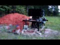
-using a HarborFreight 6.5HP motor to power block press with log splitter two stage hydraulic pump -[1]
-7gpm pump does well, but probably could have gone with 8-13gpm


-using snap acting/limit switch [2] mounted with magnets from local home store for stopping the travel of the main cylinder drop, now the only thing that I'm using the pressure switch for is the compression step. Getting very consistent block heights with this method.


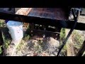
-added a few mixing paddles to get a more consistent mix, picture will come later
January 10, 2016
-Tried a grate at the bottom of the mixer/hopper with about 1" between bars. Works, and keeps out rocks, but gets clogged too much.
-have to be careful putting in cement, because if you put all of the cement on one side of the hopper it doesn't mix with both sides.
September, 2015
-Video update

THUR AUG 20, 2015
-Video update

-Code that I'm working on that uses the Arduino Micro for the CEB Press with mixer module, based on original code by several others ((see CEB_Press_6_-_Controller_Module_-_3D_CAD) (WKJCEB.ino)
-The hydraulic motor on the mixer causes some pressure spikes, this necessitates some extra delays, de-bouncing, etc.)
-File:WKJCEB MIXERMODULE ARDUINOMICRO.INO
Fri April 3, 2015
CEB Press
- THIS IS THE STEP FILE FOR THE CURRENT HOPPER PRESS THAT I HAVE. THIS MAY BE THE SAME STEP FILE AS THE OFFICIAL ONE LISTED ON THE DEV. PAGE.
- Updated 4/3/15 - latest file - File:01-001-00-6.stp:

With Mixer Module
Differences
Outside of different hopper design - the other differences are: The only difference in the frame of the mixer version is that there is one extra hole in the primary arms, and one of the guards has some extra cutouts. The hopper support tubes are also slightly different.
-THIS IS THE STEP FILE THE CURRENT DESIGN FOR THE PRESS WITH THE MIXER MODULE CURRENTLY UNDERGOING TEST.
Download STEP file for FreeCAD - File:01-001-01-6 MIXER MODULE 11-2-14.STP:
Download FreeCAD file - File:CEB Mixer.fcstd

Design Rationale
Build Pictures - [3]
- The Rotor blade design, which is attached to the shaft in the middle of hopper, and attached to the outer diameter of rotor sweep on the outer edges of hopper - allows for a complete sweep of the hopper - no soil buildup in corners of cylindrical hopper
- Anti-symmetric rotor blade design allows for soil sweeping into the middle - as soil from the far ends of the hopper is moved towards the middle.
- Reinforcement in middle of rotor blade to strengthen the rather thin blade.
- Hopper reinforcement gussets on outside of hopper are not evenly spaced with the outer edges but instead slighly closer to the center of the machine - because - the only reason those gussets are placed where they are is so that they surround the opening at the bottom of the hopper. The entire hopper is made out of 1/8" material. The only thing that is 1/2" is the base plate, which I think is the exact same base plate as on previous builds. I may have to add some reinforcement around the rim, we'll see.
- Tines are or are not twisted or bent? - Those tines are actually flat and they are just welded at off angles. It took me a while to get them adjusted so they don't rub on the hopper, but I haven't tried them with soil yet.
- How do you bend the hopper into shape? - I was actually able to form the large hopper part over the edge of a table. I had them cut slits in it, per the cut file, so that it actually forms into the multi-sided shape that you see in the model, so it is not exactly a smooth curve. Then I went back and welded the slits so it would be more solid. Then the gussets constrain it's final shape. I think I'll add some tongue and slot to the model of this hopper, because I found out, after the fact, that that would have helped.
- Geardown to slow down the auger spin speed - what are the details of geardown and spin speed? -That is something that I'm interested to see. The specs on the 7cu-in motor that I found at the shop says that the motor can get down to 65rpm. Since the sprockets are 10tooth and 60tooth, I might be able to turn the mixer as low as 11rpm. I may have the motor hooked up and running in the next two weeks, so we'll see what happens.
Do the tines need bending and/or twisting, or are they flat?

Inner gussets towards centerline of machine instead of evenly spaced from edges of hopper because they are thinner (1/8") than edge (1/4"):

Geardown of auger - 5x or so:

Design Review
Outside Review
Anecdotal evidence says that AECT had an auger in their big hopper, but it was removed because it didn't work. And that Powell and Sons may also have a hopper.
1. "Augert will suck all the juice out of your hydraulics" - I don't think that is an issue with proper control timing. We have excess hydraulic flow during the motion of the secondary cylinder - which can be used to move soil.
2. "Requires larger hopper when in fact soil just needs to flow smoothly in the hopper" - Our goal is to help move the soil, as we know that soil does not always want to move smoothly.
3. "Soil should be mixed properly BEFORE it goes in the hopper." - This is true in all cases.
4. "The conveyor really helps us get a uniform (no stones no clods) soil mix into the reduced hopper--and we only turn it on to load dirt for 50 blocks and so it takes no hydraulics away from pressing." - I guess Dan discovered free energy on this one:)
Marcin:
Dan did a conveyor:
http://propagelleprojects.blogspot.com/2014/06/the-conveyor-unveiled-and-on-site.html
Before than, an auger in hopper- http://propagelleprojects.blogspot.com/2014/02/auger-added-to-ceb-brick-machine.html
And mini tines in hopper - http://propagelleprojects.blogspot.com/2013/04/test-blocks.html
Rob:
Thanks, this is good info. I've read a few of Dan's blogs but I want to go back and take a look at more. I have thought about a lot of these things, and that is correct I will probably have to make sure that I'm not compressing and mixing at the same time. I may even end up doing some kind of conveyor like this to use either after the mixer or to feed the mixer. The design of this mixer may make it a little difficult for my tractor to load it while it is mounted to the machine, since my loader is small. The diameter of the blades on this mixer should be 24in, if I remember correctly. I'm figuring on only loading the mixer about half way, but I'm not sure what it will be capable off. Just to keep the soil from bridging the auger may not have to be big at all, even closer to 10in diameter.
Just for future reference, I've seen some hoppers at asphalt plants that have conveyors under them. Sometimes, what they do on these large hoppers to keep them from bridging is that they have a "dancer" plate. The dancer plate is just one wall of the hopper that is hinged and is actuated to move in and out/oscillate.
Build with Mixer Module - Rob Beddingfield
MON SEPT 29, 2014
-Material for the press build arrived today.
-
-I plan on building the brick press with a prototype mixer module.
-
SUN MAY 18, 2014
-Current FreeCAD Feasibility
I have spent about 20 to 30 hours of the past few weeks in order to test the current capabilities of FreeCAD and also in order to learn the basics of FreeCAD. My impressions are that the FreeCAD team has accomplished a few things that only large teams of full time programmers have accomplished in the past. The conclusion I came to after doing my best to familiarize myself with all of the tools that are available in the latest release of Free-CAD is that until FreeCAD releases their planned "assembly module", designing a machine with multiple parts may not currently be a good fit for FreeCAD.
Right now FreeCAD would be my preferred open source program to design an accurate 3d parametric model of a part for printing or machining and for opening step files for some basic inspection. (the measuring tool seems to have limited ability to measure between lines and faces of parts only measuring from point to point) The latest version has even added the ability to make 2d drawings with title blocks and projections of 3d models. The sketching and extruding/cutting tools seem to be very powerful, but without using some fairly complex work-arounds, it's my opinion that it would not be possible to design individual parts based on the geometry of other individual parts in a reasonable amount of time.
I am very interested to see what the FreeCAD development team comes up with in the next few years. I was going to try to model a small assembly to show how freeCAD could help design a functional box whose parts could be exported to a lasercutter; but it became evident that, while possible, it would have required a few work arounds and more time than I currently have at my disposal.
wed MAY 14, 2014
-FREECAD TUTORIALS
-https://www.youtube.com/watch?v=CTEPu50bG4U (draft views)
-https://www.youtube.com/watch?v=SIEaoubaipE (exporting dxf draft views)
TUE MAY 13, 2014
-FREECAD TUTORIALS
-http://www.youtube.com/watch?v=lfinO3EGXeo (placing parts, no sound)
-http://www.youtube.com/watch?v=zeQrGj5hiOA (basics, boolean, refining)
-http://www.youtube.com/watch?v=YnbjOlpGGzI (alignment)
APR 25-28 2014
-BRICK PRESS WORKSHOP AT FACTOR-E-FARM
THUR APR 17, 2014
-HARDWARE AND DRAWINGS
WED APR 16, 2014
-ADDED SCALE DIMENSIONS TO CUT SHEETS
MON AND TUES APR 14, 2014
-DXF FILES
THUR APR 10, 2014
-COMPLETE MODEL, WITHOUT HARDWARE
WED APR 9, 2014
-
TUE APR 8, 2014
-MODEL WITH MODIFIED HOPPER SUPPORT, GUARD, VALVE BRACKET, AND SADDLE -File:01-001-00-6.stp
-
-
-NOT SURE IF THIS IS THE BEST WAY TO DO THIS HOPPER SUPPORT HOLDER, BUT THIS IS WHAT I HAVE RIGHT NOW
-
MON APR 7, 2014
-1/2" STEEL MODIFIED, NEXT IS GUARDS AND GRATE
-
SUN APR 6, 2014
-
FRI APR 5, 2014
-
-
-
-Media:main assembly 4-5-14.stp
FRI APR 4, 2014
-NEW CONCEPT FOR SHAFT SUPPORT.
-
-
MON MAR 31, 2014
-NEW LINEAR BUSHING.
-
WEEKEND MAR 29, 2014
-MODIFIED CEB PRESS ASSEMBLY TO PLACE PARTS ON THE XYZ ORIGIN FOR EASY MODIFICATION
-MODIFIED FRAME TO SPREAD OUT 1/2" ON BOTH SIDES
-MODIFIED HOPPER TO 5FT WIDTH
-MODIFIED SOIL GRATE SPACING AND PLACEMENT
THU MAR 28, 2014
-SHAFT WIPER -[http://www.mcmaster.com/#9403k61/=ra9vwp ]
TUE MAR 26, 2014
-UPDATED DRAWING FILES AND CUT DATA CEB Press/Current Downloads
MON MAR 25, 2014
-UPDATED SOIL DRAWER FOR HOLE AND TAB CONSTRUCTION
-UPDATED STL FILES FOR PLASTIC PARTS ON CEB Press/Current Downloads
WEEKEND MAR 22, 2014
-MODIFY SOILD DRAWER BASED ON TECH REVIEW
-MODIFY LINEAR BEARINGS FOR 1IN SHAFT
THUR MAR 20, 2014
-STARTED CONFIGURATION 01-001-01-06 TO MODIFY HOPPER (STEEPER SIDES)
WEEKEND MAR, 15 2014 - MONDAY
-MODIFY SOILD DRAWER FOR TAB CONSTRUCTION
-UPDATED DXF FILES
THUR MAR 13, 2014
-UPDATED DRAWING 01-026 IN THE ZIP FILE UNDER CURRENT DRAWINGS. CEB Press/Current Downloads
-CALCULATED MATERIALS BASIC ESTIMATE ON MASTER BOM SPREADSHEET
SAT MAR 1, 2014
-BUILT A SMALL PRESS FOR TESTING SANDY SOIL. COMPRESSION CHAMBER IS 50MM X 100MM FOR COMPRESSIVE TESTING. SEE STP FILE BELOW FOR 3D MODEL.
-
-
SAT JAN 11, 2014
FINSIHED 2D DRAWINGS FOR NEW ASSEMBLIES
UPDATED PAGE: CEB Press/Current Downloads
-STILL NEED TO PUT STL FILES ON THIS PAGE FROM BELOW
-THIS SHOULD CONTAIN UP TO DATE CAD FILES, DXF CUT FILES, ETC.
THU JAN 9, 2014
REVISED FILES
File:01-222-00-0.STL 3D MODEL, PLASTIC BUSHING BLOCK, CLOSED
File:01-230-00-0.STL 3D MODEL, PLASTIC SHAFT MOUNT
File:01-232-00-0.STL 3D MODEL, PLASTIC BUSHING BLOCK, OPEN DESIGN
File:.5IN STEEL LIBRARY.dxf 1/2IN STEEL LIBRARY FOR CNC CUTTING, REVISED SOIL DRAWER AND ARMS
SAT-SUN Dec 29, 2013
CEB GUIDE ASSEMBLY

Mon Dec 16, 2013
CEB LINEAR RAIL
SUN Dec 15, 2013
CEB LINEAR RAIL
Mon Dec 9, 2013
Reviewing CEB_Press_6
SUN DEC 8
- CNC CUT PART FILES
SUN DEC 1
- BILL OF MATERIALS FOR CEB PRESS, AND PDF CAD FILES
Media:01-001-00-5 CEB PRESS PDF FILES.ZIP
Media:01-001-00-5 BILL OF MATERIALS.ODS
Media:01-001-00-5 -STEP 214- 12-1-13.STP
DOZUKI LINK: OSE DOZUKI
WED NOV 26
- DXF FILES FOR 01-149-00-3 GUIDE ASSEMBLY
Media:01-149-00-3 DXF FILES.ZIP
Media:01-149-00-3 2D DRAWINGS.PDF
SUN NOV 24
- FINGER AND SLOT CONSTRUCTION DESING FOR GUIDE ASSEMBLY

TUES NOV 19
- DESIGN PROPOSALS FOR SOIL DRAWER GUIDE, PROPOSAL 1 COMPLETE
SAT NOV 16
- PREPARING FINAL DRAFT AND BILL OF MATERIAL
THU OCT 23
- TWEAKING MAIN FRAME ASSEMBLY, HOLES, ETC.
- 2D ROUGH DRAFT COMPLETE
- Media:01-001-00-5 10-23-13 ROUGH DRAFT.PDF
WED OCT 16
ceb 2d drawings
SAT OCT 12
backhoe drawings just incase it might help someone
FRI SEP 27 - SAT OCT 5, 2013
- Departed Sep 26 for FeF to help with microhouse build, arrived Fri 27. Left to return home 10/4, arrived home on 10/5.
WED SEP 18, 2013
- WORKING ON 2D DRAWINGS FOR CEB (DETAILS FOR MAIN FRAME ASSEMBLY)
TUE SEP 11, 2013
- WORKING ON 2D DRAWINGS FOR THE PAST FEW DAYS
- NEED TO GO BACK AND PUT IN MATERIALS
- NEED MASTER BOM
FRI Aug 30, 2013
- Revised placement of soil grate
THUR Aug 29, 2013
- Soil Drawer Example - File:Soildrawerassy.pdf
- modified wiki page for "cad standards" (part naming)
- ceb press model/drawings
Aug 26-28, 2013
- Organizing subassemblies
- 2d drawings
examples (unfinished): File:Main assembly example.pdf File:Main assembly example 2.pdf
SUN Aug 25, 2013
- STARTED WORK ON 2D DRAWINGS
TUE Aug 20, 2013
- PLACED PARTS AND UPDATED THE MODEL FOR THE CONTINUOUS HINGES (HINGE LENGTH?)
WED Aug 14, 2013
- Finished inserting all cnc cut parts into the 3d model
- the existing compression chamber spacer does not seem to fit the mounting holes in the new cnc cut part.
TUE Aug 13, 2013
- 3D MODEL HOPPER ASSEMBLY
SAT Aug 10, 2013
- I'm not sure how to place items L-O15 and L-O16, see pic below as to my guess (yellow part), but it appears that these new parts are wider than the hopper supports,I'm sure I'm missing something.

- I'm not sure how parts L-O12 and L-O14 are placed to make the valve mount, maybe someone has a picture.

- I may have placed item L-O7 in the wrong place, see pic below (yellow part)

Thu Aug 8, 2013
- MADE 3D MODEL - CAM CLAMP ASSY
- HAVE QUESTIONS ABOUT SENSOR CLAMPS
- HAVE QUESTIONS ABOUT VALVE MOUNTING CLAMPS
- NEED PICTURES OF ALL THREE INCLUDING CAM CLAMPS
TUE, 6 Aug
- CEB V SOIL SHAKER 3D MODEL
MON, 5 Aug
- CEB V Hopper Supports 3d model
SAT, 4 Aug
- CEB V Arm assemblies 3d model
THU, 1 Aug
- CEB V drawer

Wed, 30 Jul
- CEB V frame - modified model for frame to reflect cnc cut parts.
- Finished core assembly, drawer assembly next
Mon, 29 Jul
- CEB V frame - modified model for frame to reflect cnc cut parts.
- still need to assemble top flange assembly
- Christmas_Gift_to_the_World
